The circuit may be built on a small IC type Radio-Shack breadboard circuit board. For this circuit, I recommend using a socket for the MAX 186 IC. Insert the IC in the socket only after the rest of the wiring has been completed and double checked for accuracy. Be especially careful to orient the IC so that the notch in in IC package corresponds to pins 1 and 20 of the socket.
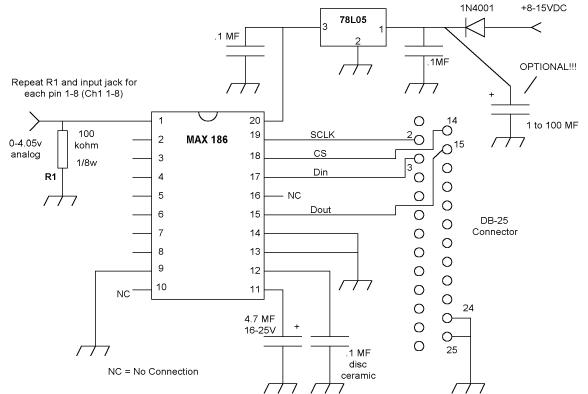
The circuit will work in the Standard version of Radio-SkyPipe, but only Channel 1 will be available. The Pro-Upgrade allows you to use any number of channels up to 8. The channels used must be sequential. Analog inputs should be restricted to the 0 to 4.095 V range.
The optional 1 to 10 MF capacitor is only necessary if the power supply is not adequately filtered.
If you have already built the similar circuit for the 8 channel ADCMAX project, you can quickly modify it by changing just three connections to the DB-25 connector. Click here for instructions on modifying that circuit.