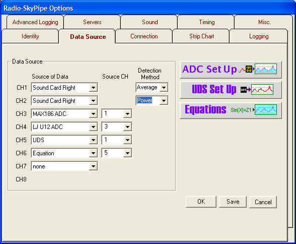
The idea behind this program is to share real world data with others. This could be temperature, radio signal strength, seismographic data, just about any physical parameter which fluctuates over time. In order to do this, the continuously changing physical parameter must be converted into a series of measurements. The Data Source options page determines the source of the data that will be displayed in each strip chart channel . Data can be taken from several different sources as determined in each channels Source of Data drop-down list.
Currently the following pre-defined data sources are:
The last two entries, UDS and Equation, are only available in the Pro Version of Radio-SkyPipe. Also the Free version is limited to a single channel so options will not appear for CH2 to CH8.
Actually there is one more item on the list; "none". When more than one channel is desired, select data sources for consecutive channels starting with channel 1. The first occurrence of a None selection in the list will stop the program from searching for additional data sources and will ultimately determine how many channels you are charting.
Sound Cards as a Data Source
The sound card has the ability to make this conversion to signals which are input to it through the line input or microphone jack, but it only works with rapidly vibrating signals like sounds. If you want to sample sound volume, the sound card is a good option as most PCs have one and there is nothing else to build or buy. If you need to measure a slowly varying voltage, as might be derived from a temperature sensor for example, you will need to use one of the ADC options unless you convert the voltage to rapidly varying signal that the sound card can detect. There are several ways to do this. If interested visit here.
R-SP Standard Edition users may use only one channel of the sound card for data collection and serving. Pro Edition users can take advantage of both channels and input a different sound signal to each channel. This might be used, for example, to display the audio outputs of two receivers set several megahertz apart in frequency. If two different channels of information are to be displayed from the sound card it is important to choose a Stereo sound format. This issue is discussed on the Sound options page help.
There are three detection methods to choose from when you use a Sound Card data source. Very briefly they are:
To read more about the detection methods and how the data is derived from the sound card visit this page, but for now understand that a detection method must be selected in association with each Sound Card data source.
Analog to Digital Converters as a Data Source
Other types of measurements can usually be converted to a voltage and that voltage can be read by an analog to digital converter (ADC). There are hundreds of these devices available and no data collection program can use them all. Originally, I decided to support just two ADCs with Radio-SkyPipe. These devices are inexpensive and simple to build. . We have plenty of documentation on how to build the MAX187 ADC, the single channel unit, right here on our website. The MAX187 ADC connects to your printer port.
You may also use the first channel of a MAX186 8 channel, 12 bit ADC with the Standard Edition of R-SP. Pro Edition users may use all 8 channels for data collection and serving data. The 8 channel ADC can build the unit from a kit. As with the single channel unit, there are plans for constructing the 8 channel ADC on this website .
Beginning with Radio-SkyPipe II, there is now support for two popular ADC units form LabJack. The LabJack U3 and older U12 devices both interface to the computer via a USB connection. There are a bit more expensive than the MAX units mentioned above (a bit over $100 USD), but have a great deal of flexibility including outputs that allow you to control relays or other devices. When combined with the Trigger capabilities of Radio-SkyPipe II a control system for various real world applications can be developed.
When you select an ADC device (other than the single channel MAX187), you also need to select which channel of the ADC to feed to the strip chart data channel. When appropriate a drop-down list appears under the Source CH column next to your ADC selection. You might for example chose to map the data from the LJ U12 channel 4 to strip chart channel 5 as shown in the example image above.
Each type of ADC has its own configuration panel that may be accessed by
pressing the Set Up ADC button. ![]()
The SkyPipe UDS Model opens the possibility for
a wide array of devices to act as data sources for the program. This is a Pro
Version feature only. Select the User Defined radio button. Press the UDS
Set Up button ![]() to configure the connection with the the UDS.
to configure the connection with the the UDS.
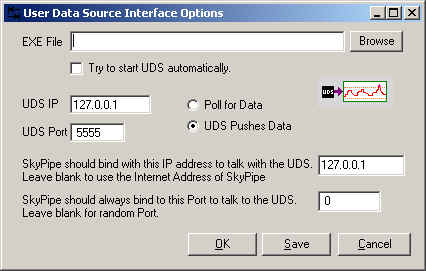 |

The IP and Port Address on the UDS must match that used by RSPII |
Browse for the UDS executable file that will act as the data source or enter the file name and path manually. Select Try to start UDS automatically if that is what you want to happen. If the UDS executable occurs on another PC and will be accessed via a network, it may not be possible to start the UDS program remotely and other arrangements for starting it may be necessary. All UDS programs communicate with R-SP via a TCP connection and TCP must be installed on your PC to use a UDS even if the UDS occurs on the same PC as R-SP. Select Poll or Push data depending on your preference (see the UDS model documentation for an explanation). Local TCP and remote TCP parameters should be entered.
Pro users may also use the result of an equation as a data source. You
may select from the 8 possible equations you have written using the data source
drop down box. Because equations may refer data in other channels, it is
not necessary that the channel have any other source of external data. For
example, your channel 3 data source could be an equation that multiplies the
data from channels 1 and 2. It is even possible to have an equation data
source that has no external source of data and is based purely on a function
applied to random numbers, or the current sample number, or part of a day.
To go to the Equation
Set Up panel press the Equations button ![]() on the lower right to reach
the panel where you may write and apply equations.
on the lower right to reach
the panel where you may write and apply equations.
Clicking Save makes your selections the defaults for the next time you start the program.
Clicking OK simple changes the settings for the session you are in.
Clicking Cancel discards any changes and takes you back to the main screen.