Sound cards have built-in analog to digital converters. Why then can't we place a DC voltage across the Line In jack of a sound card and measure it? You can't do this because sound cards are designed to capture AC voltages and have a capacitor in series with the input. AC voltages can pass through the blocking capacitor but DC voltages cannot.
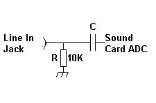
Figure1. Sound Card Input.
The figure above shows a “typical” sound card input, though there are many variations. There is often a resistor across the input forcing an input impedance of around 10K. C prevents passage of DC to the amplifiers and analog to digital converters that make up the sound card input. Some experimenters have managed to place a jumper across the blocking capacitor to allow DC to reach the sound card. However, this does not always work as the following circuitry contain other AC blocking components or may be adversely affected by the new DC path to ground at its input. An interesting article on this type of modification may be found at: http://www.qsl.net/om3cph/sb/dcwithsb.htm
Another approach to using the sound card to measure DC voltages can be had by adding some circuitry that converts the DC signal to AC. The amplitude of the AC signal needs to be proportional to the DC signal and this might be had by “chopping”, that is turning off and on, the DC signal. You need some sort of oscillator to operate a switch that accomplishes this chopping function.

Figure
2. Basic Chopper.
In Figure 2. we see a slowly changing DC voltage
applied at A (red). This voltage gets interrupted by a switch that is toggled by
an oscillator. The resulting wave is very similar to a square wave shown at B.
After passing through the blocking capacitor to the sound card the waveform can
become a little distorted due to the filtering imposed by the resistor and
capacitor, however, what is most important is that the resulting chopped signal
is proportional to the applied DC voltage.
My vote for the best chopper circuit around is the Cheap Chop by Marko Cebokli. The Cheap Chop incorporates a single, inexpensive 74HC4066 quad switch integrated circuit and a few resistors and capacitors to make a two channel chopper. The circuit works very well. It is simple enough that it would make a good beginners electronic project.
Marko also offers a small C program for Linux users that reads the sound card signal, filtering it for the chopped frequency before extracting the voltage. The advantage of using bandpass filtering in the software is that it reduces any effects from extraneous noise. The disadvantage is that the oscillator must keep within the filter's bandpass or the result will be less than optimal.
Other circuits are of course possible, for example you could use a 555 timer for an oscillator and an FET for a switch. It occurs to me that if you have a full duplex sound card you play a square wave tone to the sound output and use that to turn off and on the FET switch, though I have not tried that. Really, the hardware is so cheap and simple it makes sense to stick with it.
One interesting possibility is that you could chop the DC signal and send it via FM radio to a remote data logging point where it would be demodulated and sent to the sound card.
You can read the chopped DC signal using Radio-SkyPipe. With the Pro version of Radio-SkyPipe you may apply a function to the incoming signal to convert the data to a voltage reading. For reading voltages this way I would suggest using the Averaging Detector under Options / Data Source. The oscillator frequency used by the chopper should be well below the sound card sampling frequency.
There is a down side to using the sound card this
way. You won't be able to use the sound simultaneously to listen to other
things. You can, however, purchase sound cards for less than $10 on ebay. You
could use multiple sound cards. Radio-SkyPipe allows you to select from multiple
cards for input.