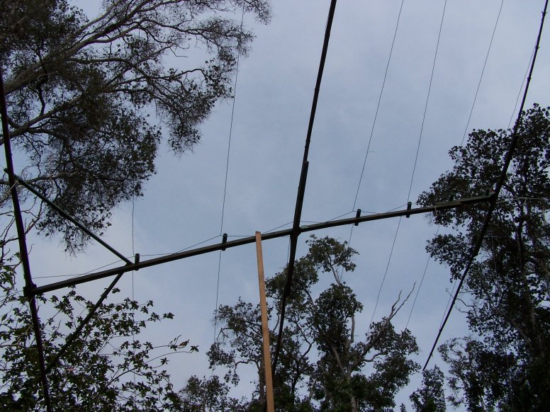
Eight element cheapo log periodic dipole array. The stick helping hold the antenna up is really more for stabilizing lateral sway. Most of the weight of the the antenna is supported by ropes strung up into the surrounding trees.
Eight element cheapo log periodic dipole array. The
stick helping hold the antenna up is really more for stabilizing lateral sway.
Most of the weight of the the antenna is supported by ropes strung up into the
surrounding trees.
This page describes my stick an wire log periodic dipole array antenna (LP) version #2. I first built this antenna in 2001 and hung it from a tall tree for Jupiter reception. That antenna was eventually destroyed by a falling branch. Here I describe its re-construction.
Perhaps the main reason someone might use an LP antenna is that it is broadband in nature. That is, you can use it to cover a wide range of frequencies. This is why they are so popular as outdoor TV antennas. The directivity of the LP antenna is better than a dipole antenna, but is less than a similar size YAGI antenna cut for a single frequency. My goal was to get a modest amount of directivity over the range of 17 to 30 MHz and to do it on a shoestring budget.
First I would like to warn you that I am not an antenna expert of any sort. My experience has largely been in building simple wire antennas and the occasional YAGI or Moxon array. I know very little about antenna modeling and have not modeled this design with an antenna analysis program. Feel free to do that if you wish. I would be interested in seeing the results. This basic design was lifted from the ARRL antenna manual, but is modified in that some of the lower frequency elements have been removed and the elements are not swept forward as in the original design. I took many liberties in construction, opting for cheap and easy wherever possible. Very often that philosophy results in disaster but this time it has yielded good results for me.
Why do I think the antenna works? I have received Jupiter on it many times. Occasionally it seems to perform as well as the commercial LP at the WCCRO, though this is hard to say for sure as local ionospheric conditions may be more responsible than anything else for this. I used an MFJ-259B antenna analyzer to chart the SWR of the antenna across the range and it looks quite good, mostly less than 2:1, (1:1 is perfect). This measurement was made at the antenna with the antenna just a few feet above the ground. (At the end of a long piece of coax the SWR of most anything looks pretty good.) The antenna seems to match well into my receivers. I am not saying this is a great antenna. I am saying it does what I want it to do. An example of a spectrogram made using this antenna and an SDR-14 receiver can be seen here.
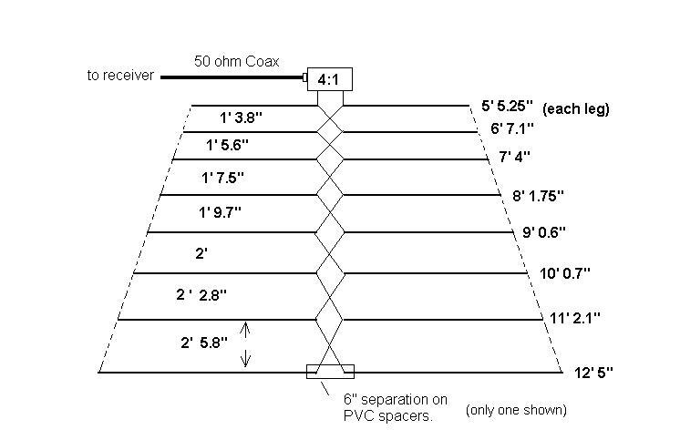
The figure above shows separation between the elements
on the left and element lengths on the right. Dimensions are in feet and
inches. Not to scale.
This LP uses wire for the dipole elements. I used stranded #14 insulated copper wire. The trick is to get the dipoles to remain pretty much in line with each other as the antenna is tilted to aim it. To do this with the minimal amount of materials you can form a stiff frame inside which the wires are strung. If you could produce a solid frame around the wires using some sort of rigid insulating material, that would be great! Then you could pull the wires tight as in a tennis racket. Such a system would be too unwieldy and difficult to make.

It is not easy to attach the bamboo spreaders directly
to the boom, so I used 2"x 2" x 4' treated lumber cross piece and a
standard construction metal bracket. The bamboo spreader can then be
screwed and tie wrapped to this cross member. The long rear element needed
more stiffening so 1"x 2" x 4' diagonal braces were added. The photo
at the top of this page shows this.
Instead I am using a central 13 foot boom made from 2"x2" treated lumber and three cross pieces made from bamboo. The shape of this wood framework is that of a standard 3 element Yagi beam. Version #1 if the LP had only two cross pieces but it was designed to be hung from a tree, with Jupiter passing almost directly overhead. Jupiter is currently (2008) at a low in declination and the LP must attain a more horizontal posture to aim towards it. Thus an additional framework element was added to help keep the wire elements better aligned. Nylon cord is strung between the tips of the bamboo elements. Most of the wire elements attach on their distal ends to this nylon cord, however, front rear and central wire elements attach directly to their corresponding bamboo spreaders with electrical tape.

Detail of the feed system. Elements are soldered
directly to the feed wires. Strip a small amount of insulation from the feed
wires and the ends of the element wires.
The elements are fed by more #14 wire strung in crossing fashion between PVC pipe spacers. The wire feeders are NOT connected where they cross between elements. You might consider adding a small PVC spacer where the feeder wires cross rather than just relying on the insulation to maintain the separation. The impedance of the array is about 200 ohms at the connection point to the feeder at the front of the array. A four to one balun circuit is used to convert the 200 ohm balanced feed to 50 ohm unbalanced coax. The balun is housed in a water-tight "Bud" box. I use an SO-239 connector on the box. The balanced feed is fed through two small holes drilled on one side of the box. Silicon is used to pad and seal the insulated wires passing through these holes. You could use binding posts or another type of feed through insulator to improve on this.

One final note. Don't be tempted to load up this antenna with your ham radio unless you are using very-very low power (QRPp)! The balun described above will not support high antenna currents. It is designed for receive-only service.
If you build this antenna or a version of it, I would like to hear about your results.